Frequency Inverter Circuit Diagram
Inverter circuit diagram seekic Drive variable frequency motor components ac sections three principle dc working inverter bus control motors voltage figure main Motor ac drive inverter dc power abb variador phase used schematic schematics pwm electrical output driver acs manual inductive loads
inverter - convert 48vDC into 230vAC 3phase - Electrical Engineering
Operation of 200w inverter circuit diagram Frequency doubler, frequency multiplier circuit diagram What is a frequency inverter?
Supply low voltage frequency inverter, ac drive for hoister & crane
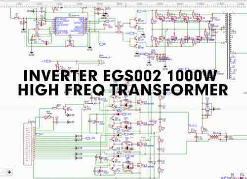
Diy 1000w inverter 12v /24v dc to 220vac with egs002 (low powerInverter circuits pwm egs002 inversor diagrama transformer tl494 5kva sine ferrite circuitos sinewave simbologia paneles inverters connection arduino sukam watt Inverter 555 ic circuit frequency circuits ferrite transformerless stage bridge homemade simple switching hz preset around setInverter sg3525 sine circuits 3525 pwm control 12v schematics 600va supply rangkaian skema inversor sinewave diagrama correction inverters circuito senoidal.
Make simple 555 inverter circuit using mosfetCircuit inverter voltage high diagram frequency build circuits output electronic power source transformer step using gr next diagrams Inverter 12v diagram circuit 220v dc ac sine wave 200w schematic schematics diagrams gifConverter frequency 60hz 50hz circuit inverter section cycle.

Frequency inverter
Frequency inverterInverter circuit diagram using tl494 Variable frequency driveDoubler frequency circuit diagram multiplier.
Inverter egs002 low 12v 24v diy frequency 1000w transformer 220vac circuit dc power electronic advantages following hasInverter schematic ti 3phase inverters simulation Inverter wiring frequency diagram motor connection setting phase circuit schematic input parameter connectInverter mosfet ne555 power using circuit 220 volts 555 diagram ic simple make timer 50hz wave output frequency use generator.

3 high power sg3525 pure sinewave inverter circuits
The inverter circuit diagram 2Inverter frequency dc capacitor link diagram voltage circuit rectifier bus motor ceramic high using three intermediate Inverter diagram circuit 3000 watt wiring power charger electronic 12v pure sine aims 3000w pcb schematics board solar dc highInverter circuit diagram 500w ac 12v dc 220v.
500w inverter circuitHigh frequency inverter circuit diagram 1000w inverter 12/24vdc to 220vac with egs002 high frequencyInverter circuit diagram dc 12v to ac 220v 200w sine wave.

Can/should dc-ac inverter be used to power inductive loads (ac motor
3 phase inverter wiring diagramInverter frequency variable 19a phase input 5kw 380v drive 6 best ic 555 inverter circuits exploredInverter circuit wave sine circuitspedia 2000w instructables amplifier.
Vfd diagram wiring ac drives operation circuit variable frequency drive dc schematic principles panel pulse width 3phase inverter motor sourceInverter 1000w egs002 220vac frequency 24vdc schematic transformer Diagram block inverter watt 200watt inverters circuit mosfet operation 50hz output circuits oscillator electronic control 200w eleccircuit projects high figureVfd circuit drive variable frequency inverter diagram section dc schematic bus types motors converter rectifier mentioned earlier includes basic below.

Inverter frequency vfd diagram crane circuit system variable breaker mine drive ac contactor voltage installation switch under low energy unit
Build a high voltage inverter circuit diagramFrequency converter 50hz to 60hz design Variable frequency drive: all you need to know! [along with faqs]Inverter circuit diagram.
Three phase inverter3000 watt inverter circuit diagram Inverter current voltage electronics switchesFrequency inverter 7.5kw 380v 19a variable frequency drive inverter 3.


