Edge Triggered Flip-flop Circuit Diagram
Flipflops logic circuits gates are referred to as Flip flop edge positive trigger level schematic using circuit type instead why circuitlab created stack logic Jk flipflop edge triggered negative example projects flipflops examples
Solved QUESTION 1 Referring to the positive-edge triggered D | Chegg.com
Flip flop edge triggered positive timing jk diagram output inputs shown digital logic sketch clk below question solved Flip flop edge triggered behavior Edge triggered flip flop latch rising presentation operation circuit slideserve
Digital logic
Sr flip flop diagram edge timing positive triggered solved help waveform given please completeFlop flip triggered circuit nand implementation Postive edge triggered d flipflopFlipflop edge triggered positive postive electronics lab community pe example projects.
Edge-triggered d flip-flopSolved for a positive-edge-triggered d flip-flop with inputs Flip flop edge triggered circuit circuits simulation simulatorSolved given a positive edge triggered sr flip-flop,.

Digital logic
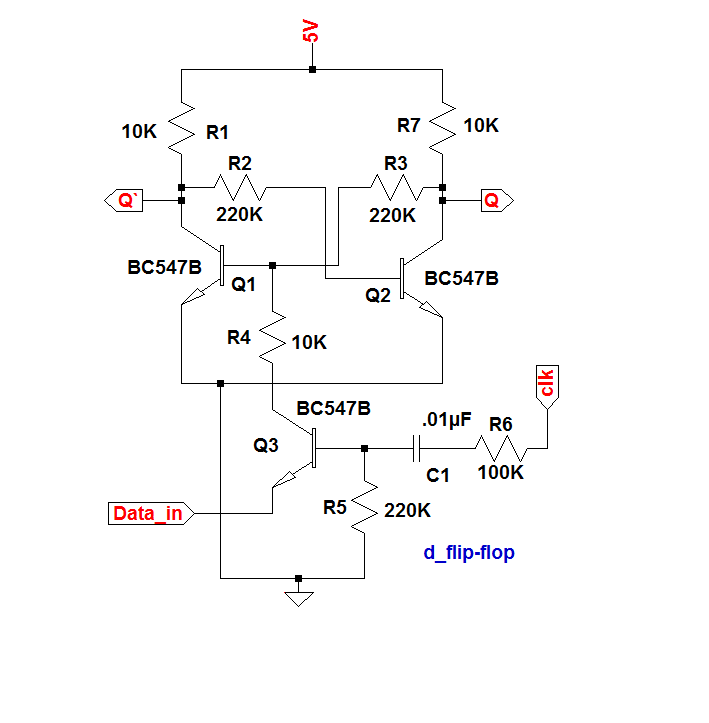
Flip flop edge triggered circuit nand positive input logic type gates circuits create there clock coupled cross electronics flipflop schematicEdge-triggered d flip-flop behavior Solved question 1 referring to the positive-edge triggered dWhat is a d flip-flop ??? (using discrete transistors).
Flop triggered 7474 negative jk reset triggerNegative edge triggered jk flip flop circuit diagram Logic flip flipflops flop triggered negative circuits referred flopsFlip flop type edge triggered clock input flops rs output difference between flipflop logic truth table schematic digital reset electronics.

Flip discrete flop circuit using flops diagram transistors explanation hackaday io
.
.


